The Dark energy of the universe
The HETDEX project is the first major attempt to find “dark energy” in the universe. With special spectrographs, the three-dimensional positions of one million galaxies are recorded. In the summer of 2012, the Hobby-Eberly Telescope will start scanning the universe – aided by maxon motors every step of the way.
The Hobby-Eberly Telescope (HET) is located at the McDonald Observatory in West Texas. Its spherical primary mirror consists of 91 identical hexagonal segments, each one meter in size. Together, these individual mirror segments form a mirror with a diameter of almost 11 m, which makes it the largest in the world. The effective aperture of the primary mirror currently amounts to 9.2 m at an opening angle of four arc minutes*. With its 11.1 m by 9.8 m, the HET is the fourth-largest optical telescope in the world. Furthermore, thanks to its innovative design, it was produced very cost-effectively: It only cost 13.5 million dollars – approx. a quarter of the cost of a comparably large telescope. These savings were made possible partly by simplifying the design and by using commercially available components.
The spectroscopic telescope for observation of the skies is mounted on a so-called Prime Focus Instrument Package (PFIP). It is equipped with two spectrographs with medium and high resolution. Even more savings have been achieved by forfeiting moving the 85-ton telescope around the second axis. That means that the mirror always looks at a position 55 degrees above the horizon, but simultaneously can be swiveled horizontally full circle. This makes it possible to observe 70 percent of the skies. The light gathered by the primary mirror is bundled above the primary mirror, where it is received by a special auxiliary lens and transmitted to the spectrographs via optical fiber. This auxiliary lens is mounted in the so-called “tracker” (see figure 3), which offers movement in 6 axes. The mirror thus does not follow the object; instead the object moves over the circle.
Currently, the wide field components of the HET are being upgraded to increase the angle of view to 22 arc minutes and the usable aperture to 10 meters. In future research projects, these upgrades will make it possible to gather the highest possible light quantity by means of a glass fibre coupling and thus revolutionise spectroscopic observations. Scientists want to use the new, upgraded HET to obtain a better understanding of so-called “dark energy”. According to the current hypotheses, almost three quarters of matter and energy in the universe consists of “dark energy”, and it is considered to be a mysterious force that causes the universe to drift apart at an increasing speed as it gets older.
HETDEX looks at the universe
The HETDEX project (Hobby-Eberly Telescope Dark Energy Experiment) was initiated to solve this mystery. From 2012 to 2015, the section of the sky containing the Big Dipper constellation will be scanned intensively with the HET. The research project aims to map 1 million galaxies that are 10 to 11 billion light years from earth – down to the smallest detail. The project is the result of the cooperation between the University of Texas (Austin), the Pennsylvania State University, the Texas A&M University, the University Observatory Munich, the Leibniz Institute for Astrophysics in Potsdam and the Max Planck Institute for Extraterrestrial Physics.
International scientists want to know more about the processes that occur in the universe. The purpose of the large-scale research project is to verify whether the current laws of gravity are correct. Another aim is to discover new astronomic details about the Big Bang. At the observatory on Mount Fowlkes in Texas, the light in the HETDEX camera is not captured by a photo chip, but instead by 33,400 glass fibers. The experts hope that, instead of dark matter, other hitherto unknown gravity effects are causing our cosmos to expand. The first evidence for one of the theses about dark matter – or an answer that conclusively proves a certain phenomenon to be non-existent – is expected for 2016 at the earliest.
Design of the PFIP
The Prime Focus Instrument Package is is positioned on a tracking device at the top of the telescope and is equipped with a wide field corrector, a capturing camera, measuring devices and a focal plane system. The PFIP is a a standalone automation unit with 12 subsystems and 24 movement axes. Motion controllers and modular I/O systems are connected using the CANopen messaging protocol. All communication between the ground-level systems and the PFIP subsystems are conducted either point-to-point via Ethernet, or through Ethernet/CAN gateways that pass CANopen messages transparently.
The PFIP has 24 motion axes, 15 of which are motorised. The movements have to be executed smoothly and with high precision at various speeds, in particular at extremely slow speeds. The motion controller has to be able to perform several operations in different situations, for example accurately following a velocity curve (aperture control), moving to and holding an absolute position, or following a multi-axial position and velocity curve.
The drives used in the PFIP subsystems are maxon motors of the brushless EC series, which can be equipped with gearheads, magnetic incremental encoders, and electrically operated brakes as required. Smooth motion at low speeds is achieved by means of sinusoidal commutation. Therefore, in addition to the standard Hall sensors installed in the brushless maxon motors, an optional incremental encoder is used. Incremental encoders provide additional position data to the motion controller.
Accurate maxon positioning control units
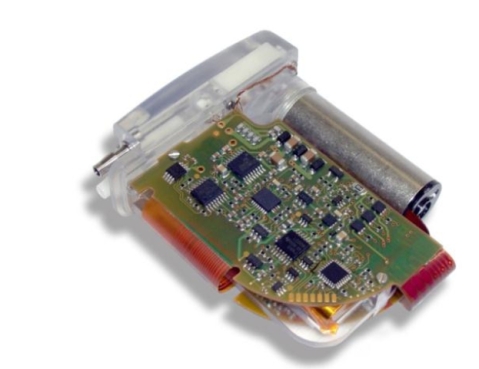
All controllers are maxon positioning control units of type EPOS2 50/5. In addition to the closed-loop control circuits for current, velocity and position, the controllers have an interpolated motion mode that enables them to follow a programmed multi-axis trajectory. Furthermore, the EPOS2 is equipped with analogue and digital input and output devices that can be accessed via the CANopen interface. It is also possible to program reactions to digital input signals, such as positive/negative limit values, home position, quick stop and drive activation/deactivation. In the PFIP application, the modular I/O stations have CANopen bus couplers,which make it possible to communicate with all additional I/O devices directly via the CAN bus or via an Ethernet-based CAN gateway. The gateway uses a simple ASCII protocol for configuration and for sending messages in both directions.
In this application, hardware devices are connected to the CAN bus and are controlled by the PFIP computer (PCC) in a master/slave configuration. In the event of multi-axis motion, the PCC would for example configure several motion controllers for the desired motion and trigger them simultaneously by means of a single CANopen command. The PFIP motion controller generally uses a 24 V DC supply. For higher inertial loads, such as the shutter, a 48 V supply can be used and is compatible to the EPOS2 50/5 controllers. Compliance with the specifications for PFIP and HET requires that all hardware components also function at temperatures of -10°C or below. maxon motor offers a wide range of products that meet these temperature requirements and provide the quality, reliability and ruggedness required for industrial automation systems.
All in all, the architecture of the HET is very flexible. By adding or removing motion controllers, I/O modules or voltage supplies, significant changes can be made very easily. The components are small and light enough to allow space in the initial design for later add-ons and supplements. www.maxonmotor.com.au

Taking to the high skies with maxon motors
At an altitude of 11 kilometres above the surface of the earth, the air is very thin. Modern pressure cabins and an environmental control system (ECS) ensure a pleasant atmosphere in commercial aircraft. In the new Boeing 787, also known as the Dreamliner, a special air-conditioning system further improves the comfort of the passengers on long flights. Brushless maxon DC motors, spur gearheads and resolver combinations ensure a good climate at great heights.
Environmental control systems in aircraft encompass three components: air exchange, pressure control and temperature control. At altitudes up to and beyond 11,000 meters, providing the passengers with the required atmosphere in the cabin, with high enough air pressure, adequate oxygen supply and a satisfactory ambient temperature, means that each commercial aircraft needs a climate control system. Air-conditioning systems in aircraft therefore differ greatly from ordinary air-conditioning systems, both where the design and the energy source are concerned, as aircraft ACs require an energy source with much higher power capacity and have to meet higher safety requirements.
Pressurised cabins in commercial vehicles ensure that the air pressure is at a level that is tolerable for passengers. The circumference of the aircraft expands due to the pressure compensation. This puts great stress on the airframe. During the flight, the pressure in the cabin is successively reduced slightly as the altitude increases. Thus the passengers experience an amplitude increase to approx. 2400 meters. However, the climate control also depends on the amount of oxygen required by a human and the number of seats on the aircraft.
But oxygen alone does not ensure a pleasant atmosphere. The temperature and humidity also play an important role. Modern computer-controlled systems regulate the temperature with a precision of one degree. A considerable amount of heat is contributed by the passengers themselves. Each person radiates 80 to 100 W on average. On the ground, the air-conditioning unit is supplied with compressed air by the auxiliary power unit (APU) and during the flight, on most aircraft, by the jet engines.
Dreamliner increases comfort of long-distance flights
Last year, aircraft manufacturer Boeing launched a new long-distance aircraft: the Boeing 787, also called the Dreamliner. Unlike any other aircraft before it, the Dreamliner fuselage consists largely of carbon fibre. This aircraft offers an improved cabin atmosphere and different pressure conditions. This makes long-distance flights more tolerable for the passengers.
According to Boeing, the new innovative plastic body of the aircraft is stronger than a thin aluminium shell. The cabin pressure corresponds to a height of 1800 m. This is deemed to be more passenger-friendly than the customary 2400 m. Furthermore, the corrosion-resistant shell allows 15 percent air humidity in the interior, instead of the customary 4 percent. Therefore the climate system also works a little bit differently.
On the Boeing 787, the air is not drawn from the jet engines under pressure, but is instead, fresh air from the outside atmosphere. On board electric motors power compressors to prepare the cabin air for a comfortable flight experience. In other words, the air-conditioning system is operated entirely electrically. The jet engines have very strong generators to ensure adequate power supply. The climate system for the Dreamliner is manufactured by the American AC manufacturer Hamilton Sundstrand. Such a system supplies enough power to cool or warm 25 private households.
maxon motors for a perfect climate
Motors for aeronautic and astronautic applications differ greatly from standard motors. They have to withstand greater temperatures and vibrations, have a longer life span and have to be very reliable. All in all, 48 motors by maxon are at work in the climate control system of each Boeing 787. Specific motor modifications were required for the highly complex air-conditioning system. This includes drives for the cabin ventilation, for cooling the electronics and for closing and opening the air inlet on the outside of the aircraft. The motors have to withstand temperatures of -55 C to +85 C and the vibrations during take-off and landing – throughout the decades of the aircraft’s service life. Therefore it is vital that the motors have a long life span. The cabin ventilation system consists of 36 shut-off valves that are driven by maxon EC 45 flat motors. These light brushless motors have been designed to fit into even the smallest spaces.
The EC flat motors achieve speeds of up to 20,000 rpm and, thanks to their open design, offer excellent heat dissipation at high torques. In the case of the climate control system of Hamilton Sundstrand, the motors achieve a speed of 4,000 rpm. In particular the stator of the flat motors installed in the air-conditioning system has been adapted; the printed circuit board has been modified with low-temperature Hall sensors and the motor has been given a special protective conformal coating. A modified stator magnetic path prevents movement when the motor is unpowered further improving overall efficiency. The linear drives for the air inlets use modified EC32 motors which have also been equipped with low-temperature Hall sensors. Furthermore there is a flame barrier at the output shaft of the motor, a special vibration-resistant fastening screw threads and cogging detent-brake modules. www.maxonmotor.com.au

Modified maxon DC Motors drive the air inlets
Motor driven automatic transfer device helps nurses.
Nurses face the daily challenge of caring for an overweight population, which leads to debilitating injuries. A new motorised lateral transfer device allows even the smallest nurse to move a heavy patient.
One of the growing problems facing the nursing career is a thinning staff, and with it the need to care for overweight patients with very little help. This effort has led to musculoskeletal disorders (MSDs) including back injuries, the most costly MSD injury. In fact, 12 percent of nurses leave the profession each year due to back injuries, and 52 percent suffer from chronic back pain. Those working in nursing homes have even a higher rate of injuries. Until recently, moving a patient was performed manually or with minimal automation.
Allowing a single nurse to safely and comfortably transfer a patient without risk of injury required a fully automated device. Astir Technologies (Concord, MA) took this on as a goal, to use the latest technologies available to provide patient transfer in a manner that decreases hospital costs and reduces injuries to health care professionals, while minimising the discomfort to the patient. With this in mind, the company designed and manufactured the PowerNurse™ for that purpose. All of the mechanisms are packaged in a low-profile (74- x 28- x 2.3-inch) assembly that rides over a standard hospital stretcher. With the PowerNurse patients can be moved between hospital beds, stretchers, imaging equipment, operating room tables, and exam tables. According to Chris McNulty, Astir Technologies President and developer of the PowerNurse, “Other less expensive friction reducing devices decrease but do not eliminate the risk of nurse injury while performing a lateral transfer.” As with other advanced designs, the PowerNurse was made possible with the advances to technologies and the miniaturisation that has taken place in recent years. A critical area evident in the device’s design is that of the DC motors and gearboxes. High power rare earth magnets and advances in motor winding have resulted in high torque motors in small packages. “Maxon leads the industry with a wide selection of high end products that made it possible to lower the profile of the PowerNurse, leading to a more comfortable and effective product,” McNulty said.
Chris McNulty’s solution involves a series of conveyor belts, DC servo motors, and electronics that fit into a thin profile that allows the transfer of very heavy weights automatically. During development of his first prototype, over 400 pounds was easily transferred using 1/5th of the capacity of the 250 Watt Maxon Brushless 45mm motors designed into the device. This meant that the 120 Watt ECmax 40 motors could be used in the PowerNurse, while the larger EC45 motors could be used for a bariatric model in development.
Originally, the PowerNurse traveled at only one speed (1 inch per second). Although this speed was fine for patient pick-up and delivery, it was too slow for the lateral transfer process.
So, Chris incorporated a two-speed option into his beta model, where the device operated at 1- or 2-inches per second. “Maxon’s wide selection of gearbox diameters, gear ratios, and number of gear stages allowed us to fine tune the products overall speed while maintaining the highest level of torque,” he said. Paring the Maxon DEC 50/5 motor control with either the EC45 or ECmax 40 motor smoothed the design as well as the overall operation of the device. The PowerNurse incorporates four ECmax 40 motors; four GP 42C, three-stage, 43:1 planetary gearboxes; and four DEC50/5 servo-amplifiers along with a 400 W, 48 VDC power supply.
A specific challenge in the development of the device concerned the drive rollers, which undergo tremendous torque delivered by the Maxon gearbox geared down even further through a 2:1 reduction to the drive shaft. This situation resulted in a lengthy process of evaluating knurled rollers, smooth rollers, and polyurethane coated rollers. In the end, the coated rollers delivered the response desired and handled the torque levels delivered by the motors very well.
An all push-button driven device requiring no software interface, the PowerNurseTM operates in three distinct modes: burrow, pad align, and transfer. During the burrow mode, belts are used to pull the patient onto the top of the device while belts on the bottom move the device under the patient. Done simultaneously, the result is the patient feels a much smoother transfer than with many other device.
In pad align mode only the top conveyor belts are energised. This aligns the patient and incontinence pad if necessary. Transfer mode energizes only the bottom belts, which transfers the PowerNurseTM, with the patient riding on top of the device, to an adjacent surface. Rotation and translation are available in any mode and the result is a tank-like translation or rotation. Four Maxon DC motors are required to achieve all of the device’s operational modes. Astir Technologies is now investigating the addition of a yaw gyro for the system, to enhance the machine-human interface and bring the motor controls to a new level of performance. This is expected to make the PowerNurse even easier to use.
For advice and assistance with your automation application or information on maxon motors contact maxon motor Australia. www.maxonmotor.com.au

Model Making: A dwarf-sized Caterpillar
Maxon drives also play an important role in model making – for example, many locomotives run their rounds powered by maxon motors. But even crazier things can be found in the world of model making: like the bright yellow Cat track loader built by Marcel Sigrist, a hobby model maker from Central Switzerland. Over a period of approx. two years, he built three true-to-life Trax Cat 983B model loaders at a scale of 1:8. These miniature excavators are driven by maxon motors.
The famed yellow Caterpillar machines are usually gigantic and awe the boy in every man. For Marcel Sigrist from Central Switzerland, nothing seemed more logical than building a model of the loader. But he was not satisfied with building a simple model of the Cat loader. After intensive research and studying the original spare parts manual with exploded views, he started planning and building the remote-controlled miniature loader based on photos and measurements taken on the “real” Cat loader. After 8 months of intensive CAD planning, the first drawing with a scale of 1:8 was finished. The model was to have dimensions of 105 cm long, 38 cm wide, 44 cm high and a weight of 70 kg.
The heart of the Cat: the drive and the electronics
As early as the planning phase, Marcel Sigrist thought of the motors and gearheads. Only maxon motors were considered for the project. The original loader uses spur toothing – therefore it was clear from the start that the model will also use this version. On each traction side, two maxon DC motors with 150 W were connected by means of a toothed belt drive and positioned perpendicularly with a 20:1 worm gear. This gives the loader the required power. A controller for track vehicle models was installed as electronic component. It has a voltage of 12 V and two times 50 A traction current. Simple maintenance of the electronics was a prerequisite for the installation. To this end, all hydraulic and electronic components were installed in a drawer system. Thus the hydraulic lines can easily be removed and all technical components can be accessed easily, in the case of an emergency, by opening the drawers. This carrier system contains the hydraulic pump with its motor, the controller for the hydraulic motor, as well as the oil tank with filler neck and deaeration equipment. The second component is the hydraulic valves with servo systems for the various functions.
The entire SMX sound module, including speakers, was also built on this unit. Two battery blocks (NiMH) with a voltage of 12 V (12 A/h) were used for the power supply. This makes it possible to operate the model track loader for up to an hour. After all parts of the mini track loader were painted, the assembly work started. After only 13 months, the first of three model loaders was finished. This was followed by a successful trial run (see figures 1,3,4).
Not even three months later, number 2 was finished, followed by model 3 a mere three months later. “What I especially liked about this project was the fact that, when I started out, nothing on this model could be bought as a prefabricated part. Planning, measuring and drawing it to get reliable construction plans was a special challenge. In spite of referencing the spare parts book, I can proudly state: I developed it myself,” says Marcel Sigrist.

Miniture loader powered by maxon DC motors
Project Pegasus: Gallop like a horse
The Pegasus robot, which was created by students of the ETH Zurich during a research project, does not have wings like the famous horse from Greek mythology. But instead, the autonomous robot has strong legs that can gallop almost like those of a horse – thanks to motors by maxon.
As part of a research project at the ETH Zurich, the autonomous robot called Pegasus was created. With its telescopic legs, it is capable of moving across vast distances. The legs are designed for moving in a dynamic trot and can achieve top performance with low energy consumption, thanks to state-of-the-art drive technology. Pegasus has a modular design and can therefore be used for a wide range of applications. Each module consists of two robot legs. Hence he can be sent on his journey with two, four or even six legs. During the time frame of the project, a total of three modules were built.
In the joint project by the ETH Zurich and the TU Delft (in the Netherlands), ten mechanical engineering students – six students from the ETH Zurich and four students from the TU Delft – together developed the autonomous robot during the last two semesters of their bachelor’s degree. The specified target was that the robot has to cover a distance of 10 km in less than 10,000 seconds (2 h 47 min., approx. 3.6 km/h) with a single battery charge. The prerequisite was that the robot has to have an extremely energy-efficient design and has to store energy, for example through the use of springs in its legs.
The project was initiated at the end of 2010. The first hopping tests were started in April 2011 – initially, only one leg was used to extensively test the jumping ability. In each leg, a maxon DC RE40 motor drives the spindle that is responsible for extending and retracting the leg (figure 3). Additionally an EC-4pole motor controls the rotational degree of freedom in the hip module (connecting part between two leg modules). Thus it is the 200 W motor that makes it possible that the entire leg can turn (figure 4).
Thanks to the special winding technology and the 4-pole magnets, the maxon EC-4pole drives are unbeatable when it comes to delivering the highest power per unit of volume and weight. The motors have no cogging torque, a high efficiency of more than 90 percent, and excellent control dynamics. The metal housing ensures good heat dissipation and mechanical stability. When it comes to service life, these motors also leave the competition far behind.
Figure 1: Leg module in detail: Encoder for the leg length (A), maxon motor for linear actuation (B), coupling (C), ball screw bearing (D), ball screw (E), tubes for linear guidance (F), end stop with damping for the spring (G), ball screw nut (H), spring (I), buckling preventer (J), spherical foot (K). The upper part (blue) and the linear drive (red) are equipped with 4 PTFE (polytetrafluoroethylene) sliding bearings and thus easily move the parts of the leg over the leg frame.© 2011 ETH Zürich
The controller
Two different positioning controllers are used to control the Pegasus robot. One of these is the EPOS 24/2 controller, which is used to control additional sensor interfaces. This position controller, like all other maxon motor EPOS products, was especially developed for commands and control functions in CANopen networks. Additionally this controller has been equipped with very good motion control functions. With the “Interpolated Position Mode” (PVT), the position controller is able to synchronously move along a path specified by means of setpoints. Secondly the EPOS2 70/10 controller is used. It is specially tailored to the brushed DC motors with encoder or the brushless EC motors with Hall sensors and encoders from 80 to 700 W. In the Pegasus system, the controller on the one hand is responsible for torque control (current mode) of the EC-4pole motors and for speed control (CANopen Profile Velocity Mode) of the used RE motors. In current mode, a constant torque can be controlled on the motor shaft. In “CANopen Profile Velocity Mode”, the motor axis is moved with a specified set speed.
The original target of the project was not achieved, due to the short timeframe. The functionality of various parts of the robot were not yet perfectly matched to each other, explains Steve Heim, former student and a member of the Project Pegasus team. The project is being further developed in the Autonomous Systems Lab (ASL) of the ETH Zurich. Since the end of last year, interns at the ASL are working on successful implementation of the project. In the mean time, the two-legged Pegasus has executed its first stable hops. The target of achieving a distance of 10 km in less than 10,000 seconds with a single battery charge is within grasp.

DC RE 40 Motor takes care of the jump motion
Medical motor pump system for improved quality of life.
Implantable pump systems are used to treat many medical conditions – including ascites. Severe disorders are frequently the cause for this symptom. To control the fluid that has collected in the abdomen, Sequana Medical has developed an active implant. In these devices, maxon brushless motors are responsible for trouble-free running and smooth pump motion.
Ascites is a term that describes an accumulation of large quantities of fluid in the peritoneal cavity. In the vernacular, this symptom is also called “abdominal dropsy”. In approx. eight out of ten cases, the cause of ascites is decreased liver function, for example caused by cirrhosis of the liver. But ascites can also be caused by reduced myocardial function, kidney diseases or cancer. For most patients, medication and a special diet are adequate to drain this fluid again. However, for several thousand of patients per year in Europe and the USA, this therapy no longer works. Per day, an affected patient can accumulate up to two liters of fluid in the abdomen. For many patients, this accumulation of fluid in the abdomen is a big burden, as hitherto the only way to remove the fluid was by means of regular tapping.
The ALFApump System, an active implant from Swiss medical technology specialist Sequana Medical, ensures that patients with ascites can lead an uncomplicated life. The system monitors the fluid accumula-tion in the abdomen and, whenever necessary, pumps the fluid into the bladder of the patient, where it is excreted with the urine. The core component of the three-part system is the ALFApump implant with the two catheters for the peritoneal cavity and the bladder. The external SmartCharger with charging station is a mobile charging and communication unit that charges the battery of the ALFApump implant and enables communication. The lithium ion battery of the pump allows autonomous operation for several days. Due to the energy consumption of the pump (per day, 0.9 liter is pumped out on average), the battery has to be charged regularly. The battery is charged wirelessly through the skin of the patient.
For trouble-free monitoring, a notebook computer is used as an additional component. By means of spe-cial communication software the physician can program the implant for each patient individually. He can precisely define how much fluid should be pumped into the bladder per day. Furthermore, the physician can use the wireless connection to access the automatically recorded data of the patient.
High material requirements
The ALFApump implant is inserted between the subcuta-neous fat layer and the peritoneum and is made of PEEK (polyether ether ketone), a biocompatible plastic. The unique ambient conditions within the human body re-quires special motors and appropriately adapted electronics, as no hermetically sealed encapsulation is possible when plastic is used. Therefore, the materials used have to withstand permanent moisture exposure and an in-creased salt concentration. Additionally, a constant temperature of max. 40 °C has to be ensured. Due to the presence of humidity, the implant is sealed completely, the electronics are protected with an additional coating and a brushless motor is used.
The complex electronics handles low-level control of the motor, control of the pump drive, evaluation of the sensor signals, communication with the SmartCharger and the battery management. Thus the gear pump also has to pump enclosed air (e.g. after an operation) in addition to fluid. Therefore, it is very important that very narrow tolerances are maintained; this in turn results in a very high torque, also during normal operation. An additional complicating factor is the fact that the fluid in the peritoneal cavity contains high quantities of fibrin and protein from the blood plasma. These can easily clot and thus severely influence the pump operation. In the worst case, the pump can get blocked completely. To prevent this from occurring, the pump performs a short movement without volume transport at regular intervals.
Motor drive for high precision in medical technology
The maxon brushless 13mm motor drives the pump gears of the ALFApump and is specially tailored to the requirements of the customer. The motor is equipped with Hall sensors that are important for position feedback. The motor controller uses these Hall sensors to achieve reliable and stable operation, in particular at low speeds and high load torques. In addition to the sterilisable motor having a special stator coating, the shaft is also made of bio-compatible materials. Additionally, special shaft geometry is required. With the compact design of the EC 13, its excellent low-noise and low-vibration running properties and the low heat emission, the drive is specially tailored to the requirements of medical technology. To increase patient safety and reduce the complexity of the ALFApump’s programming, an in house processor is used for the motor controller. The main processor configures the motor controller, to achieve the desired volume transport. This motor controller checks whether the respective parameters are valid.
If, for example, there is a deviation from the maximum permissible pump duration, the main processor de-energizes the motor subsystem. Thanks to this dual processor system, maximum monitoring during the pumping procedure is guaranteed and the highest possible level of safety is provided.
Successfully implanted pump systems
The first two commercial operations with the pump system were performed in October 2011 in Vienna (Austria). According to Prof. Markus Peck-Radosavljevic, Vice-Chairman of the Division of Gastroenterology and Hepatology at the Department of Medicine III of the Vienna General Hospital, both short operations were completed without complications. “I believe that the ALFApump system is a real breakthrough in the treatment of ascites. The patients can lead an easier life, as they do not need to go to hospital for the strenuous drainage procedure,” says Peck-Radosavljevic.
Contact maxon motor Australia for further DC motor information.

The inside of the gear pump with electronics and maxon DC motor.
Keeping muscles in shape.
For paraplegic people, rehabilitation is frequently a long process; this is why methods and technology that optimise these measures for the patient are so important. At the Bern University of Applied Sciences, many years of research has led to the development of a recumbent trike with electrical stimulation. The patient’s movements are supported by a maxon flat motor.
Cycling with a recumbent trike can partially restore lost motor functions of patients with spinal cord lesions. Furthermore, it provides the patients with a very practical and successful basis for cardiopulmonary and muscular training units. The paralysed leg muscles are reactivated by means of functional electric stimulation (FES) combined with controlled training.
At the Institute for Rehabilitation and Performance Technology (IRPT) at the Bern University of Applied Sciences, scientists and students perform research to further develop the rehabilitation method. The core competencies of the IRPT are cardiopulmonary and neurologic rehabilitation after strokes or spinal cord injuries, as well as feedback systems, automation and control of modern training devices. Procedures and systems are developed in an interdisciplinary team in cooperation with Swiss industrial companies and rehabilitation clinics. In October 2009, Kenneth Hunt, Professor for Rehabilitation Technology, became Director of the Institute for Mechatronic Systems at the Bern University of Applied Sciences. At the beginning of 2011, he founded the new Institute for Rehabilitation and Performance Technology. The Scottish-born expert in the field of rehabilitation was co-founder of the “Scottish Centre for Innovation in Spinal Cord Injury” in Glasgow and left his mark on the Centre as inaugural Director of Research. Furthermore he gained first-hand experience in the industry during his five years of working at the Department of Research and Technology of Daimler-Benz AG in Berlin.
„The recumbent trikes are suitable for per-sons who suffer from paraplegia, a stroke or childhood-onset cerebral palsy. “We use methods and technology from the field of competitive sport to improve the rehabilitation process of people who suffered accidents or diseases,” explains Kenneth Hunt. FES was already used on the first generation of recumbent trikes, but at this stage no motors were used yet. The new generation is equipped with an electric motor that provides additional power to supplement the FES. FES alone can only generate a low power of 30 to 40 W, which means that the max. power and duration of use is very limited.
Drive components for effective support of the leg power
The electric motor is needed to support the stimulation at the beginning. This means that the drive keeps the legs of the patient in motion. Furthermore the drive represents the controlled training unit that switches back and forth between brake/generator mode depending on the performance of the patient. The maxon motors are installed in the front section of the trikes, in the pedal bearings.
Accordingly, the requirements to the electric motors are high – both where the size and the power is concerned. The motor and gearhead has to fit between the pedals to keep the system as compact as possible. According to Kenneth Hunt, the maxon motors and the matching gearheads meet these requirements. The brushless maxon EC flat motors are the perfect solutions for many applications, thanks to their flat design. The 90 W flat motor used in the recumbent trike furthermore provides enough power for the application. The power is supplied by a battery that, in addition to the motor, also supplies the rear wheel hub with power.
Drive and brake in one
In the controlled training units, the motor initially moves the legs of the patient, before the muscles are stimulated. The more active the patient is, or the more muscle power is generated by means of the stimulation, the less support is required from the motor. As soon as the muscles generate enough force to move the legs autonomously or to work against a load, the motor acts as brake. For this reason, a 4Q control device is required for switching between motor and brake operation. A brake chopper is used for brake operation to eliminate the generated energy. The interaction between motor/brake and FES is controlled by special software that has been written at the Institute and that runs on a computer or micro controller.
Contrary to customary bicycles, the pedals and drive wheel of the trike are not connected by a chain. Both parts are decoupled from each other, so that such a chain is not required. The pedals and the drive wheel are only “coupled” by means of the control software. This provides a high level of flexibility, as the motion dynamics can be programmed by the software and adapted in real time. Two prototypes of the recumbent trike have already been completed for research purposes: One system for adults and one for children. Both systems are already completely functional, but still have to be clinically tested by patients. Large clinical studies conducted with the FES system (without motor) in the past have shown that the fitness of the patients is improved, the bone density in the large leg bones is increased and the paralysed musculature is built up again.
After clinical testing has been completed, the plan is to commercialise the new generation of recumbent trikes as well, with the assistance of an industrial partner. Furthermore additional modifications and optimisations are planned for the recumbent trikes.

maxon expands extreme motor range
Technical advances made by maxon motor while customising a brushless motor for operation in deep oil boreholes are to be rolled out in a new, heavy-duty motor range, designed for the harshest conditions on earth. and beyond.
Already widely used in fields as challenging as space, robotics and Formula 1, maxon accepted the challenge of creating a small motor reliable enough to operate at depths of 5,000m.
The resulting motor, maxon’s award-winning EC22 Heavy Duty, features important refinements to its rotor, winding, magnets and bearings; enabling it to survive temperatures as high as 240°C and operate happily at 200°C and atmospheric pressures from high vacuum to 1,700bar (25,000psi).
The project involved maxon constructing an entirely new testing laboratory, complete with extreme temperature facilities and vibration rigs. Here – and throughout extensive field trials – the 22mm motor was proven to perform despite vibration of up to 25grms, and resist impulse and impact forces of 100G: 50 times those undergone by maxon’s motors in jet fighters and Grand Prix cars.
Moreover, testing while fully submerged in oil revealed its initial 80-watt output rating in air could comfortably be trebled under such conditions, because of vastly improved heat dissipation.
Now, in response to requests from engineers, maxon will incorporate the same modifications into 16mm, 32mm and 42mm versions of the HD motor, covering a broader range of applications. with further developments promised in the near future.
maxon’s senior sales engineer Paul Williams oversaw development of the successful EC22 HD.
He explains: “A lot of engineers were already pushing our motors to the limits of their operating tolerances, so the EC22 HD has opened up new possibilities; not just in oil exploration, but all manner of fields where performance under extreme temperature, pressure or vibration is important.
“Around 50% of our motors include custom specification, and in this case that’s helped us to make real leaps forward in rotor technology and glue-less construction, as well as and other refinements.
“These new motors will make those capabilities available to a wider range of engineers, and will doubtless inform our mainstream production in the future.
“Of course, the story doesn’t stop there. Our challenge now is to go even further, broaden the range and hopefully push on towards 300°C!”

Tiny DC motors drive high-speed pipettes
With the aid of maxon’s small, powerful brushed DC motors, Intellepro has developed an innovative compact multi probe pipette system to speed up research.
The new pipette system is 30% more effective than traditional pipette automation and will allow labs to process samples more quickly and efficiently than ever before.
While the concept is simple enough, several significant design challenges needed to be surmounted in order for the system to work in practice. One of the most important requirements was adequate motor thrust, enough to overcome pierceable foil and caps, while the device’s acceleration and deceleration speeds needed to be slow enough to prevent liquid from splattering.
maxon RE13 DC brushed motors were chosen to satisfy the size and torque requirements of the end product. The RE13 motors offer the user up to 2.8 mNm of torque. They also work within an ambient temperature range from -20 to 65 degrees C.
These moving coil motors, with Neodymium magnets, are particularly designed for long life, low electrical noise, and high efficiency.
Smoothness of operation and freedom from cogging was also critical to avoid impeding the motion of the pipette probe, leading to measuring errors. The RE13 DC motor’s ironless rotor design removes this issue, enabling the motor to be controlled easily and accurately.
The planetary gear reduction and encoders integral to the system allow the motors to facilitate excellent servo control and minimal backlash, resulting in high positioning accuracy and long life.
According to Don Rich, IntellePro’s project engineer, “Without the power and compactness of the maxon motors this product could not have been built.”

